A hydraulic directional control valve is a key component in a hydraulic system used to control the flow direction of hydraulic oil. Its working principle is based on the movement of the valve core within the valve body to change the on/off state of the oil circuit, thereby realizing the reversing, starting, stopping, or speed regulation of actuators (such as hydraulic cylinders and hydraulic motors).
Its core mechanism can be broken down into the following key components:
1. Structural Composition
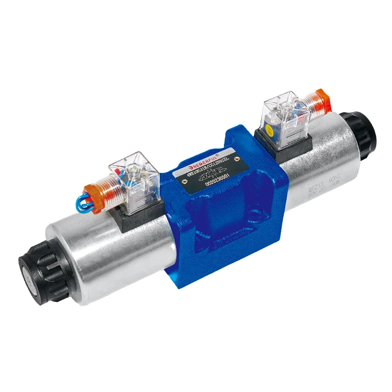
A hydraulic directional control valve mainly consists of a valve body, valve core, spring, electromagnet (or manual control mechanism), and seals. The valve body has multiple oil passages, and the valve core switches the connection between these passages by moving. Depending on the control method, it can be divided into electromagnetic directional control valves, manual directional control valves, and hydraulic directional control valves, among which electromagnetic directional control valves are the most widely used.
2. Working Process
Taking an electromagnetic directional valve as an example, its working process can be divided into the following steps:
Initial State: When the electromagnet is not energized, the valve core remains in its initial position (e.g., neutral position) under the action of the spring force. At this time, hydraulic oil flows only through a specific oil circuit (e.g., the return oil circuit), and the actuator is in a stationary or unloaded state.
Reversing Action: When the electromagnet is energized, the electromagnetic force overcomes the spring force and pushes the valve core to move, changing the oil circuit connection mode. For example, the valve core moving to the left may connect the inlet port to port A of the actuator, while port B connects to the return oil port, thereby driving the hydraulic cylinder to extend; conversely, it drives the hydraulic cylinder to retract.
Holding State: When the electromagnet is continuously energized, the valve core remains in the new position, and the actuator continues to move; after de-energization, the valve core resets under the action of the spring, and the actuator stops or moves in the opposite direction.
3. Control Methods and Classification
Electromagnetic Control: Directly drives the valve core to move by switching the electromagnet on and off. It has the characteristics of fast response speed and precise control, and is suitable for scenarios with a high degree of automation.
Manual Control: The valve core is operated directly via a handle or lever, suitable for situations requiring manual intervention, such as equipment debugging or emergency operation.
Hydraulic Control: The valve core is actuated by hydraulic oil pressure, suitable for high-pressure, high-flow systems or scenarios requiring remote control.
4. Performance Parameters and Industry Standards The performance parameters of hydraulic directional valves directly affect system efficiency and reliability. Common parameters include:
Nominal Diameter: Determines the oil flow rate; common specifications are 6mm, 10mm, 16mm, etc.
Working Pressure: Typically 0.15MPa to 35MPa, selected according to system requirements.
Switching Frequency: High-frequency directional valves (e.g., 5 times/second) are suitable for rapid-action scenarios, but valve core wear must be considered.
Sealing Performance: Employs O-rings, combined gaskets, and other structures to ensure no leakage, conforming to international standards such as ISO 5598.